


Author: ZanRobot 服務員
嘗試在Virtual box中的Arduio IDE測試esp32的教學範例,驗證OK,但上傳時總是出現錯誤:Permission denied: ‘dev/ttyUSB0’,似乎無法開啟序列埠。請問可知是何原因?
本範例主要是針對Arduino (ESP32)單晶片使用單核心情況下,往往因為delay指令,讓程式在執行過程中產生暫停或卡住,須等delay的時間過後,主程式才能繼續進行。這樣會造成其他需要同步偵測的感測器或驅動的程式無法進行,並造成程式執行的不順利或停頓現象。
以下我們介紹Arduino提供的 millis()指令,讓你的程式不中斷,繼續跑,並且不會卡住。並以一個鐵路平交道的情境為例,用鍵盤J按下後作為觸發訊號(模擬火出通過),LED燈開始閃爍,蜂鳴器也同步動作,經過一段時間後同時結束,可重複上述情境。
使用零件 :
以下是程式碼供參考 : @Z機研工作室 提供。
bool execute_alert_procedure = false;
int execute_alert_procedure_Time = 0; //一次警報的時間 或 警報週期
int buzz_Pin = 14;
int execute_buzz_time=0;
bool execute_buzz = false;
int Led_Pin = 13;
int execute_Led_time=0;
bool execute_Led = false;
void setup()
{
UserControlInit();
pinMode(buzz_Pin, OUTPUT);
pinMode(Led_Pin, OUTPUT);
}
void loop()
{
MessageRead();
if (execute_alert_procedure){
if((millis()-execute_alert_procedure_Time)<10000){ // (現在的系統時間 – 開始執行警報的系統時間)< 10秒 ; 10秒可以自行修改 if((millis()-execute_buzz_time)>500){ // buzz 發聲的頻率
if(execute_buzz){
digitalWrite(buzz_Pin, LOW);
execute_buzz = false;
}else{
digitalWrite(buzz_Pin, HIGH);
execute_buzz = true;
}
execute_buzz_time = millis();
}
if((millis()-execute_Led_time)>500){ // LED 亮滅的頻率
if(execute_Led){
digitalWrite(Led_Pin, LOW);
execute_Led = false;
}else{
digitalWrite(Led_Pin, HIGH);
execute_Led = true;
}
execute_Led_time = millis();
}
}else{
execute_alert_procedure = false;
digitalWrite(Led_Pin, LOW);
digitalWrite(buzz_Pin, LOW);
}
}
}
// UserControl
void UserControlInit(){
Serial.begin(115200);
}
// 讀取鍵盤觸發指令
void MessageRead(){
if (Serial.available()){
MessageProcessing(Serial.read());
}
}
// 判斷鍵盤命令並設定開始警報的時間
void MessageProcessing(char data){
Serial.print(data);
if (data == ‘j’){
execute_alert_procedure = true;
execute_alert_procedure_Time = millis(); // 設定每次開始警報的時間=當下Arduino晶片的絕對時間
}
}
// ———–
其他參考 :
https://www.arduino.cc/reference/en/language/functions/time/millis/
就如同各位從零開始的夥伴們,你們一定很想快點看到,一台可以裝上雷射LiDAR導航,自主漫遊 + 路徑規劃 + 自主避障 + 影像AI &^$%^#%%^%^&%^ ~ 等等集合了目前self-driving 前端科技的家用小車八 !! 我們記錄一位工程師,他是如何從零開始的學習、蛻變到一位 self-driving developer的過程。
話說,這一開始的動作應該也是記錄摸索的過程,不過,這卻是最真實的、殘酷與慘痛代價的經驗。希望這些記錄可以減少後面跟進的學習者們寶貴的時間。
在此定義初階段的學習標的 :
1-1、連線準備
使用裝備 :
測試架構 :
1-2、上傳程式碼
小編不再多寫,可參考官網 :
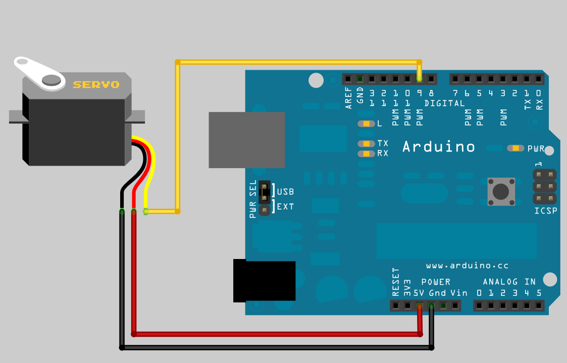
This should open the following code in your IDE:
   1 /*
   2  * rosserial Servo Control Example
   3  *
   4  * This sketch demonstrates the control of hobby R/C servos
   5  * using ROS and the arduiono
   6  *
   7  * For the full tutorial write up, visit
   8  * www.ros.org/wiki/rosserial_arduino_demos
   9  *
  10  * For more information on the Arduino Servo Library
  11  * Checkout :
  12  * http://www.arduino.cc/en/Reference/Servo
  13  */
  14
  15 #if defined(ARDUINO) && ARDUINO >= 100
  16   #include "Arduino.h"
  17 #else
  18   #include <WProgram.h>
  19 #endif
  20
  21 #include <Servo.h>
  22 #include <ros.h>
  23 #include <std_msgs/UInt16.h>
  24
  25 ros::NodeHandle  nh;
  26
  27 Servo servo;
  28
  29 void servo_cb( const std_msgs::UInt16& cmd_msg){
  30   servo.write(cmd_msg.data); //set servo angle, should be from 0-180
  31   digitalWrite(13, HIGH-digitalRead(13));  //toggle led
  32 }
  33
  34
  35 ros::Subscriber<std_msgs::UInt16> sub("servo", servo_cb);
  36
  37 void setup(){
  38   pinMode(13, OUTPUT);
  39
  40   nh.initNode();
  41   nh.subscribe(sub);
  42
  43   servo.attach(9); //attach it to pin 9
  44 }
  45
  46 void loop(){
  47   nh.spinOnce();
  48   delay(1);
  49 }
程式碼扼要說明 :
11行 : 建立一個callback 函式 servoCb (被呼叫後立即返回),該函式是給subscriber使用的,函式的寫法是固定的, type of message is std_msgs::UInt16 ,message name 是 toggle_msg。這個callback函式很單純沒有參考回傳的內容,只是很單純地每次收到一個message,Arduino就會閃爍或熄滅一次LED。
15行 : 建立一個接下來可執行的 publisher或 subscriber。在這裡,我們建立一個subscriber,topic name 是 “servo” , type 是 std_msgs::UInt16。對於訂閱(subscriber)者,必須記住根據訊息(message)來訂閱。最後的兩個參數, Its two arguments are the topic it will be subscribing to and the callback function it will be using.
接著,執行程式
Now, launch the roscore in a new terminal window:
roscore
Next, run the rosserial client application that forwards your Arduino messages to the rest of ROS. Make sure to use the correct serial port: (要注意喔)
rosrun rosserial_python serial_node.py /dev/ttyACM0
再開一個 terminal,
rostopic pub servo std_msgs/UInt16 <angle>
就如同各位從零開始的夥伴們,你們一定很想快點看到,一台可以裝上雷射LiDAR導航,自主漫遊 + 路徑規劃 + 自主避障 + 影像AI &^$%^#%%^%^&%^ ~ 等等集合了目前self-driving 前端科技的家用小車八 !! 我們記錄一位工程師,他是如何從零開始的學習、蛻變到一位 self-driving developer的過程。
話說,這一開始的動作應該也是記錄摸索的過程,不過,這卻是最真實的、殘酷與慘痛代價的經驗。希望這些記錄可以減少後面跟進的學習者們寶貴的時間。
在此定義初階段的學習標的 :
我們就從 “ROSSerial_Arduino測試 (ROS通訊點亮Arduino LED實驗)” 開始吧 !
1-1、Arduino IDE安裝與設定
安裝好後,最後會在桌面上看到Arduino的圖案。
1-2、連線架構
使用裝備 :
測試架構 :
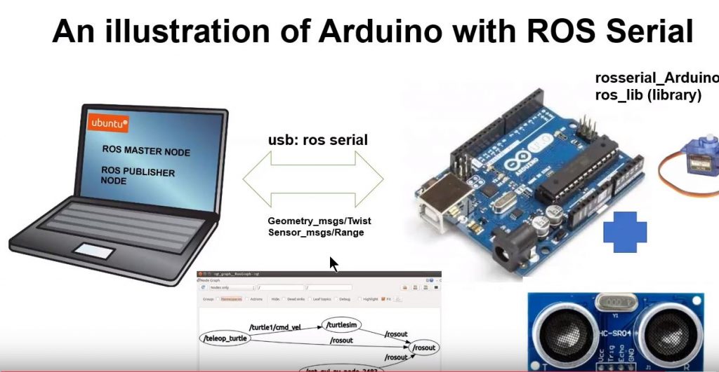
筆電中的VM環境再貼一次 :
1-3. 介紹ROS Serial
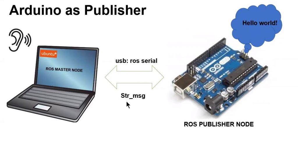
參考官網 。若是你想用Arduino來做ROS的通訊模組 (也就是作為一個ROS nodes),包括publish, subscribe ROS的messages, publish TF transforms 和 get the ROS system time。 rosserial provides a ROS communication protocol that works over your Arduino’s UART. rosserial_arduino package, you can use ROS directly with the Arduino IDE. 喔! rosserial 這個函式庫下面有許多packages,目的就是在不同硬體系統中,可以容易地運行一個ROS node。
1-4. 安裝軟體
有兩步驟 : 先安裝自己的ROS 工作站 ,再安裝 ros_lib 在自己的Arduino IDE環境中。
1-4-1. 安裝自己的ROS 工作站
官網有兩種方式,一個是安裝編譯好的binaries code,另一種是從source code先編譯再安裝,我們選擇第一種(官方建議的)。
You can install rosserial for Arduino by running:
sudo apt-get install ros-melodic-rosserial-arduino
sudo apt-get install ros-melodic-rosserial
你可以把 melodic 換成你自己的ros 版本如 indigo 等
再來到 /libraries 下面檢查是否事先有ros_lib資料夾,若是有先delete掉。
  cd ~/Arduino/libraries
  rm -rf ros_lib
  rosrun rosserial_arduino make_libraries.py .
以上完成後,就可在 /ibraries 下面找到 ros_lib的資料夾
開啟Arduino IDE ,檢查以下是否存在。
PS : 目前,另一種更簡單的作法,就是如果你不想花功夫針對你的ROS工作站去做完全安裝,你只是要可以在Arduino上跑ROS的通訊協定,你可以採用以下 :
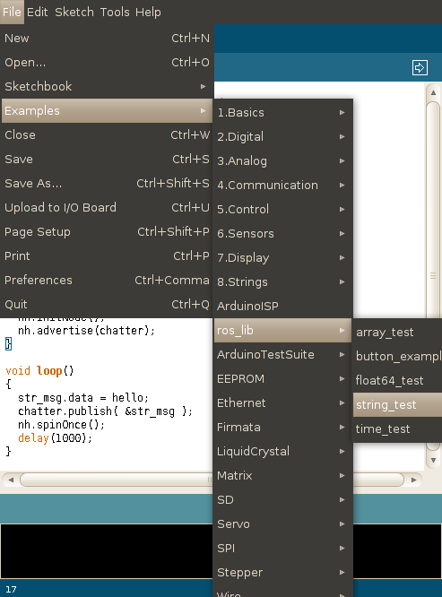
*Note: Currently you can install the Arduino libaries directly in the Arduino IDE. Just open the Library Manager from the IDE menu in Sketch -> Include Library -> Manage Library. Then search for “rosserial”. This is useful if you need to work on an Arduino sketch but don’t want to setup a full ROS workstation.
1-5. 測試 Arduino 的 Hello World (example publisher)
參考官網
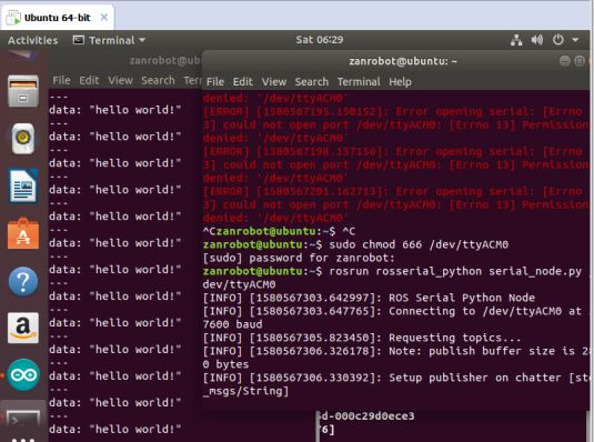
先燒錄Arduino程式,第一次可能會出現 ” can’t open device “/dev/ttyS0″: Permission denied ” ; 處理方式,
sudo usermod -a -G dialout <username> , 其中 username 用你Linux的帳號,我自己是 zanrobot ; 完成後先logout出系統,再 login一次。此時,再燒錄Arduino時就不會有問題。
接著當以下 :
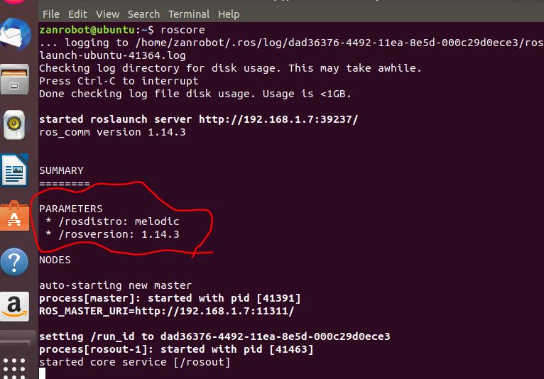
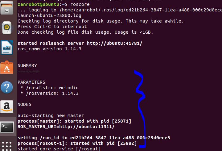
Now, launch the roscore in a new terminal window:
roscore
Next, run the rosserial client application that forwards your Arduino messages to the rest of ROS. Make sure to use the correct serial port:
rosrun rosserial_python serial_node.py /dev/ttyUSB0
此時,又會出現
[ERROR] [1580567065.273146]: Error opening serial: [Errno 13] could not open port /dev/ttyACM0: [Errno 13] Permission denied: ‘/dev/ttyACM0’

此時,處理一下 serial port權限的問題,
sudo chmod 666 /dev/ttyACM0測試最後的結果,如下 : 在 VM上的node,可以收到Arduino 發佈出的文字訊息 “hello world” !
就如同各位從零開始的夥伴們,你們一定很想快點看到,一台可以裝上雷射LiDAR導航,自主漫遊 + 路徑規劃 + 自主避障 + 影像AI &^$%^#%%^%^&%^ ~ 等等集合了目前self-driving 前端科技的家用小車八 !! 我們記錄一位工程師,他是如何從零開始的學習、蛻變到一位 self-driving developer的過程。
話說,這一開始的動作應該也是記錄摸索的過程,不過,這卻是最真實的、殘酷與慘痛代價的經驗。希望這些記錄可以減少後面跟進的學習者們寶貴的時間。
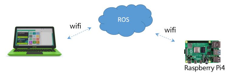
1-1、遠端遙控機器人 – two ROS machines 通訊測試
在此定義初階段的學習標的 :
我們就從 “two ROS machines 通訊測試 (小烏龜遠端連線)” 開始吧 !
1-2、連線架構
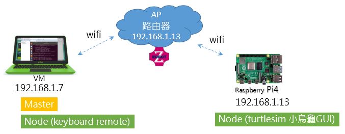
使用裝備 :
測試架構 :
 1-2、VM(虛擬機)設定網路連線
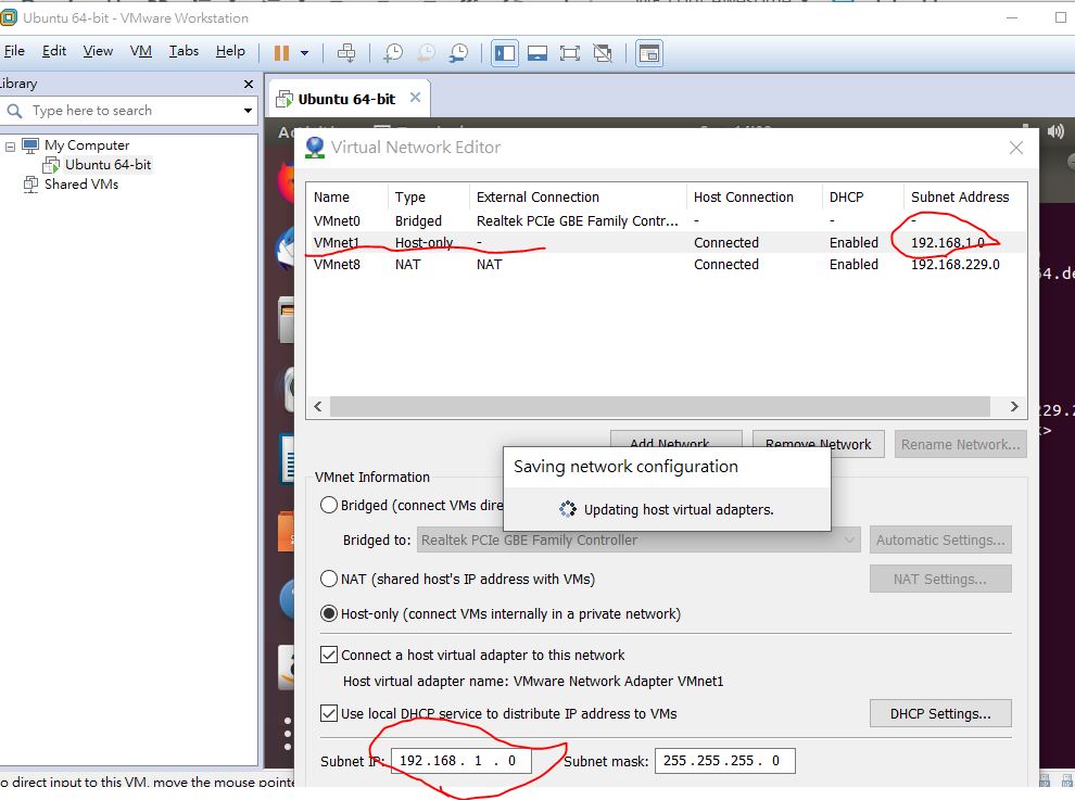
先去 Edit –> Virtual Network Editor… 指定你要用哪個虛擬機,本次用內建的VMnet1,隨即檢查它的內建分配網域,要改成192.16.1.o 的網段,以便跟目前測試網路AP所分配的IP同一個網段。 如下
接著到我們的開啟的虛擬機,去選擇 “virtual machine setting” ; 這裡我們選 Custom – VMnet1 ,來使用我們自己設定的虛擬網路
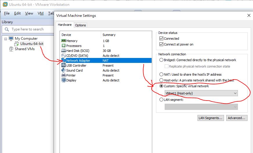
這時,你會發現 vm中的 VMnet1被分配到 192.168.1.128。 當然,若是你要自己指定其他網路等級的ip 如 10.42.xx.xx ,也可以如上圖自己指定。
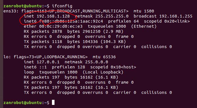
此時,到pi 的終端機去檢查有無連上vm裡面的ubuntu,如下 ping 192.168.1.128。同樣地,也從vm中ping一下pi看看有無正確連上。

此時本網路個裝置測試的ip 如下 :
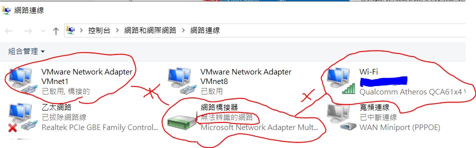
通常在vm設定虛擬網路的時候,許多人會出現問題 ,請務必檢查電腦端網路橋接的結果要正確 :
如下圖,網路橋接器的裝置名稱,不可以是”無法辨識的網路”,否則橋接wifi 實體網卡仍然是不成功喔 !
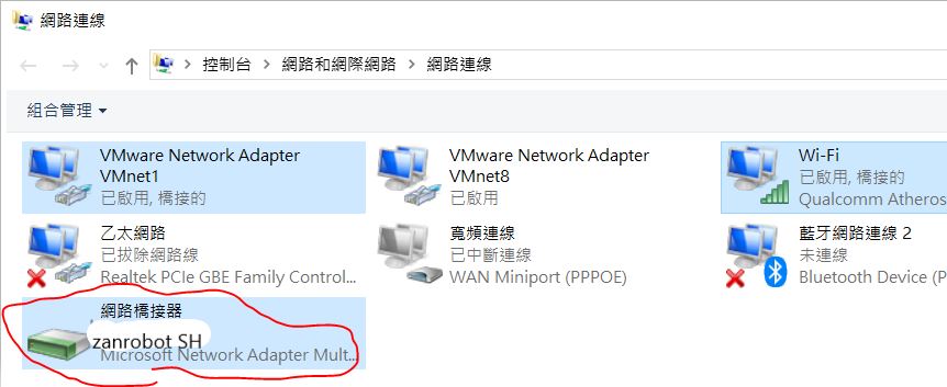
成功的話如下圖 :
1-3. 指定ROS管理資訊發佈與接收訊息的Master機器
ROS的通訊架構其實很簡單,就像遊戲中的角色扮演,你要台ROS機器擔任甚麼角色都可以,只要一開始指定清楚即可,本次架構如下:
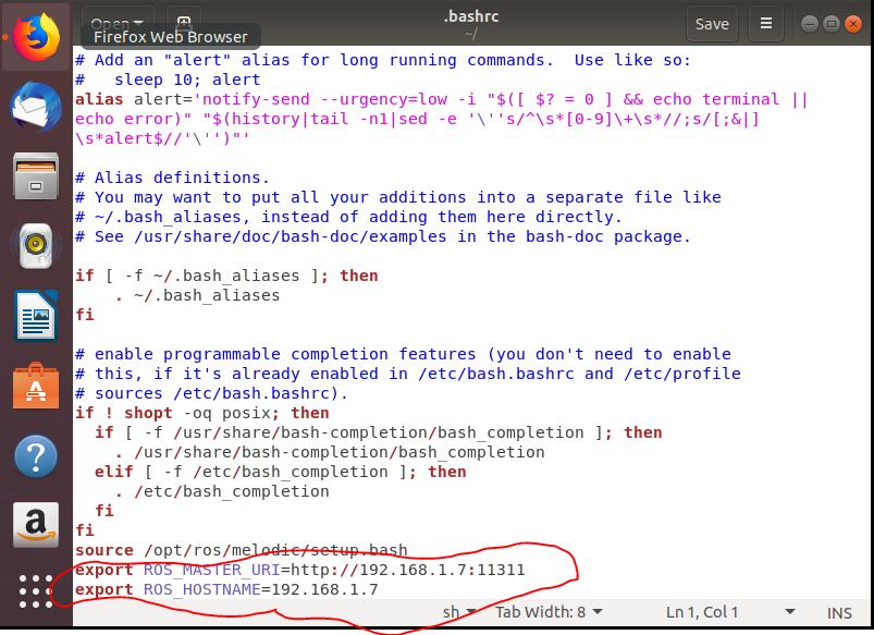
1. 編輯vm虛擬機器端的環境變數設定檔。
我們需先開起虛擬機器上的 Terminal ,輸入指令進入其中的環境變數設定檔。
使用 gedit 編輯環境變數設定檔指令:sudo gedit ~/.bashrc
檔案開啟後,在最後面加上兩行敘述,如下
export ROS_MASTER_URI=http://192.168.1.7:11311
export ROS_HOSTNAME=192.168.1.7
同樣地,在pi4 上面執行上述動作,增加以下兩行
export ROS_MASTER_URI=http://192.168.1.7:11311
export ROS_HOSTNAME=192.168.1.13
2. 在VM虛擬機中開始遙控小烏龜
先在區域網路上註冊一個 Master。註冊 Master 指令 : roscore 。我們選PC的VM虛擬機來註冊master

2. 樹莓派端執行 turtlesim_node 節點。執行 turtlesim_node 節點
指令 : rosrun turtlesim turtlesim_node
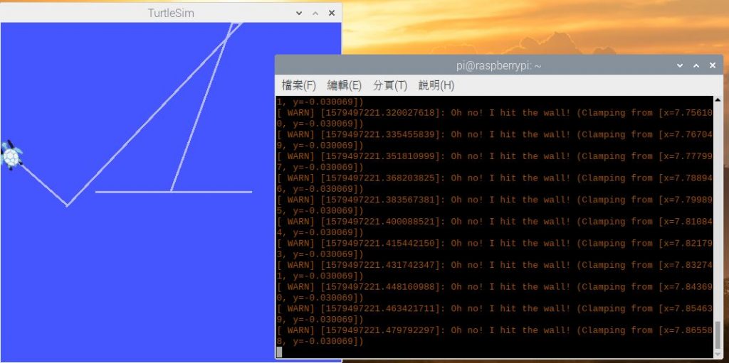
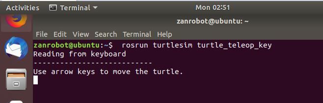
3. 虛擬機器執行 turtle_teleop_key 節點。要再開一個新的terminal,執行 turtle_teleop_key 節點
指令 : rosrun turtlesim turtle_teleop_key
以上就是所有的動作了。祝各位順利 !
就如同各位從零開始的夥伴們,你們一定很想快點看到,一台可以裝上雷射LiDAR導航,自主漫遊 + 路徑規劃 + 自主避障 + 影像AI &^$%^#%%^%^&%^ ~ 等等集合了目前self-driving 前端科技的家用小車八 !! 我們記錄一位工程師,他是如何從零開始的學習、蛻變到一位 self-driving developer的過程。
話說,這一開始的動作應該也是記錄摸索的過程,不過,這卻是最真實的、殘酷與慘痛代價的經驗。希望這些記錄可以減少後面跟進的學習者們寶貴的時間。
0-1、如何接近ROS ?
在此先定義這個初階段的學習標的 :
我們就從 “ROS遠端遙控機器人” 開始吧 !
0-2、遠端遙控之系統架構
使用裝備 :
測試架構 :
筆電端 : 經過資料蒐集與無數次的誤打誤撞後,決定灌 VM 走 ROS Melodic Morenia。參考以下
官網資訊說明 Melodic 是最新持續update。
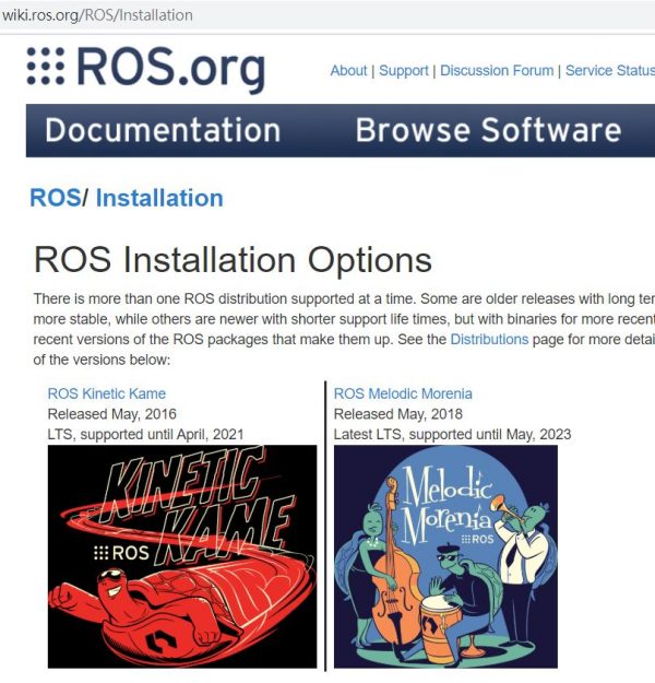
根據官網說法,
“ROS Melodic installation instructions
These instructions will install the ROS Melodic Morenia distribution, which is available for Ubuntu Artful (17.10), Bionic (18.04 LTS) and Debian Stretch, among other platform options.
0-3、win10 筆電安裝VM (虛擬機)進行ubuntu環境安裝
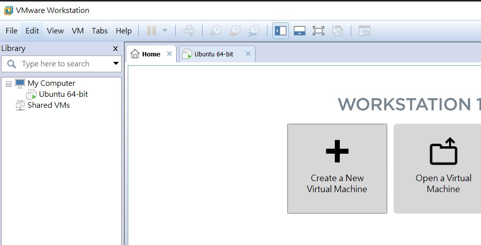
我們決定先用PC安裝VM環境,如下 :
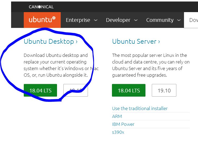
到Ubuntu官網下載 18.04LTS 印像檔 (ubuntu-18.04.3-desktop-amd64.iso ) , 約2.3G 下載時間約需 40分。
到VM中,點選 “Create a New Virtual Machine” ,一個按鍵可以安裝完成Ubuntu 18.04系統。不過系統安裝時間也約需40分鐘。
0-4、安裝 ROS Melodic Morenia
請到ROS官網,按照步驟操作 :
按照下面的選項, “source code” 要勾一下,下載地點可依據下拉選單,選擇 “Select Best Server”,系統會自動去測試哪個server下載比較快。


選完下載伺服器後,點 “close”,接著會問是否要更新清單,選 “Reload” 來更新倉庫清單。
Select “Close” to save your changes. A dialog box should appear, asking whether you’d like to update the list of repositories. Select “Reload” to update the list.

接著在 Alt+Ctrl照做以下動作。 refer to : http://wiki.ros.org/melodic/Installation/Ubuntu
Setup your computer to accept software from packages.ros.org.
sudo sh -c 'echo "deb http://packages.ros.org/ros/ubuntu $(lsb_release -sc) main" > /etc/apt/sources.list.d/ros-latest.list'
|
Source Debs are also available |
sudo apt-key adv --keyserver 'hkp://keyserver.ubuntu.com:80' --recv-key C1CF6E31E6BADE8868B172B4F42ED6FBAB17C654
If you experience issues connecting to the keyserver, you can try substituting hkp://pgp.mit.edu:80 or hkp://keyserver.ubuntu.com:80 in the previous command.
Alternatively, you can use curl instead of the apt-key command, which can be helpful if you are behind a proxy server:
curl -sSL 'http://keyserver.ubuntu.com/pks/lookup?op=get&search=0xC1CF6E31E6BADE8868B172B4F42ED6FBAB17C654' | sudo apt-key add -
First, make sure your Debian package index is up-to-date:
sudo apt update
There are many different libraries and tools in ROS. We provided four default configurations to get you started. You can also install ROS packages individually.
In case of problems with the next step, you can use following repositories instead of the ones mentioned above ros-shadow-fixed
Desktop-Full Install: (Recommended) : ROS, rqt, rviz, robot-generic libraries, 2D/3D simulators and 2D/3D perception
sudo apt install ros-melodic-desktop-full
or click here
Desktop Install: ROS, rqt, rviz, and robot-generic libraries (~ 我們這裡用這個 ~ 耗時30分)
sudo apt install ros-melodic-desktop
or click here
ROS-Base: (Bare Bones) ROS package, build, and communication libraries. No GUI tools.
sudo apt install ros-melodic-ros-base
or click here
Individual Package: You can also install a specific ROS package (replace underscores with dashes of the package name):
sudo apt install ros-melodic-PACKAGE
e.g.
sudo apt install ros-melodic-slam-gmapping
To find available packages, use:
apt search ros-melodic
It’s convenient if the ROS environment variables are automatically added to your bash session every time a new shell is launched:
echo "source /opt/ros/melodic/setup.bash" >> ~/.bashrc
source ~/.bashrc
To install this tool and other dependencies for building ROS packages, run:
sudo apt install python-rosdep python-rosinstall python-rosinstall-generator python-wstool build-essential
Before you can use many ROS tools, you will need to initialize rosdep. rosdep enables you to easily install system dependencies for source you want to compile and is required to run some core components in ROS. If you have not yet installed rosdep, do so as follows.
sudo apt install python-rosdep
With the following, you can initialize rosdep.
sudo rosdep init
rosdep update
到此為止,ROS算是安裝完成了。
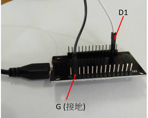
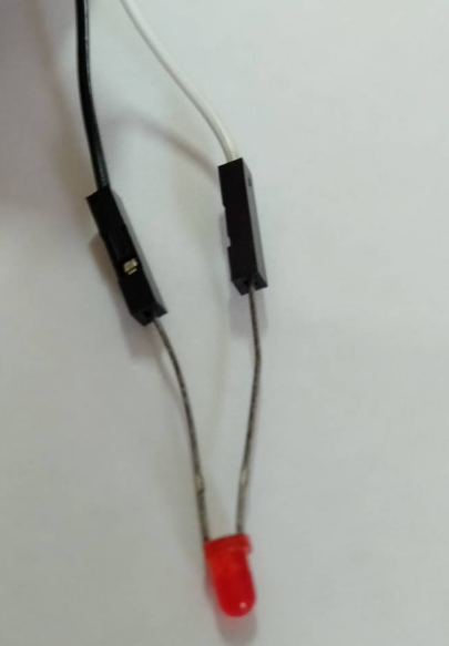
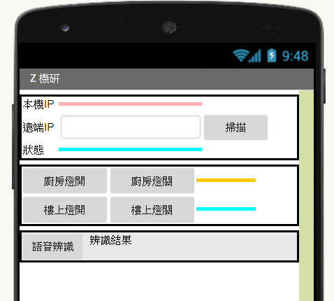
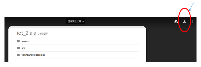
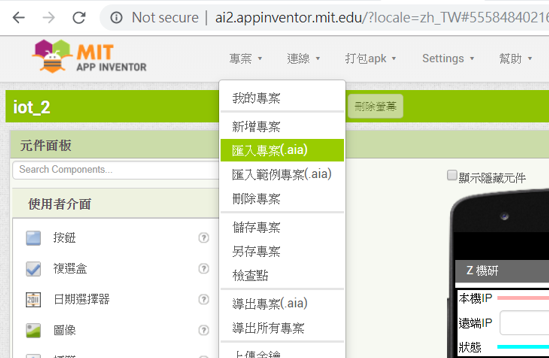
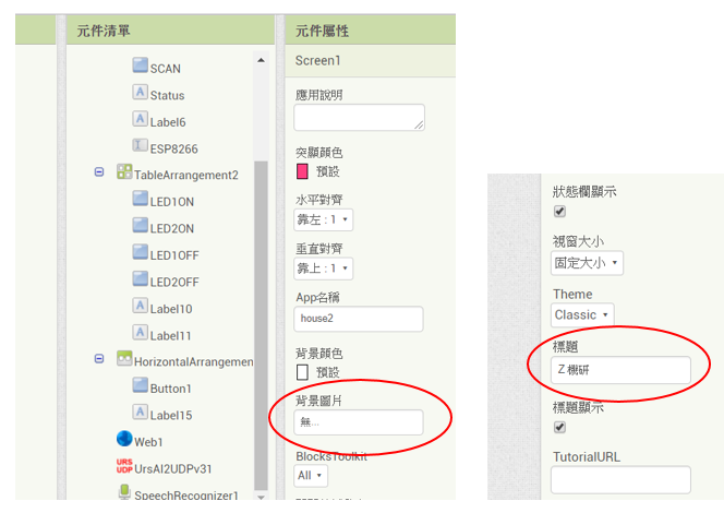
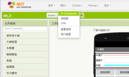
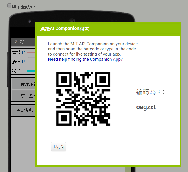
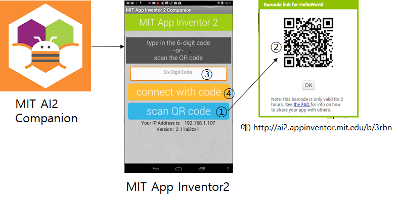
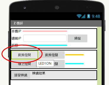
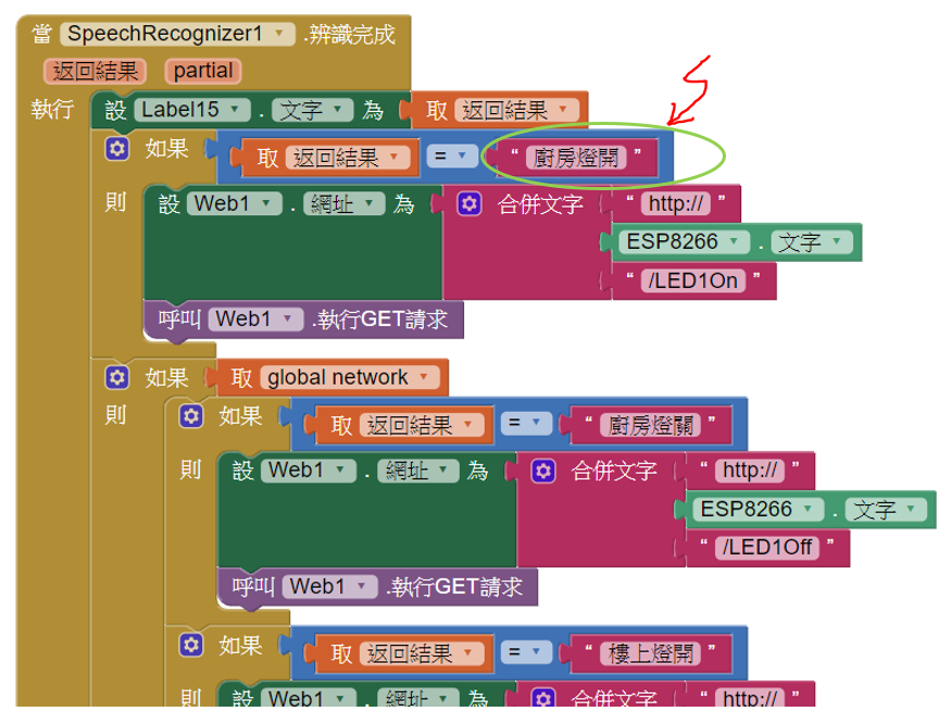
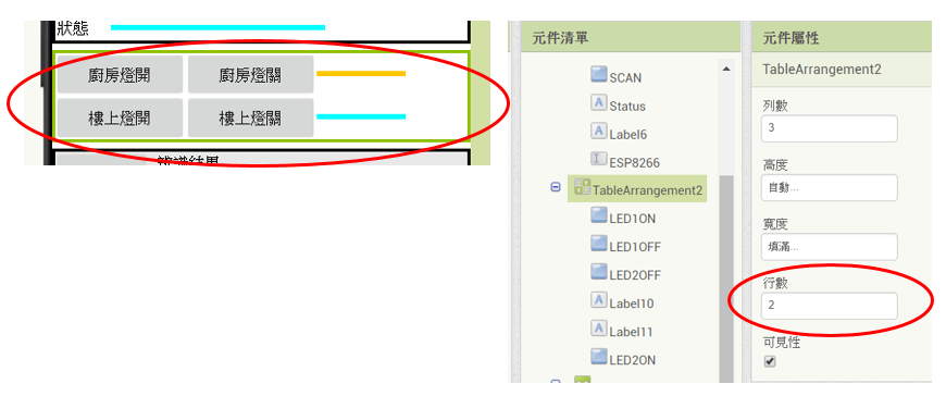
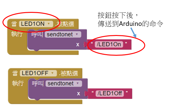
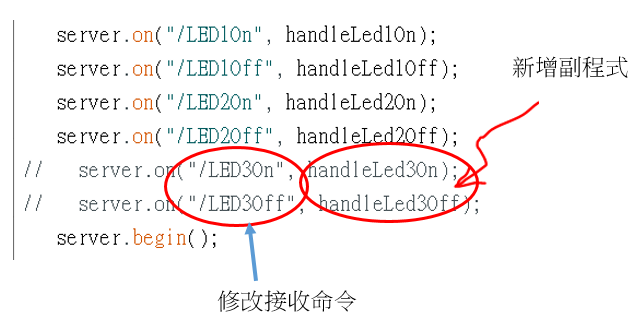
本文是利用Arduino系列的NodeMCU Lua (Esp8266) wifi 模組來製作簡單的App Inventor 手機程式,並用按鈕(Button)和語音辨識的方式來控制LED或電燈開關。 更令人興奮的是硬體材料費不到 NT200 !! 以下整理3 hr上課內容給各位參考,以搭配您的課程需要。
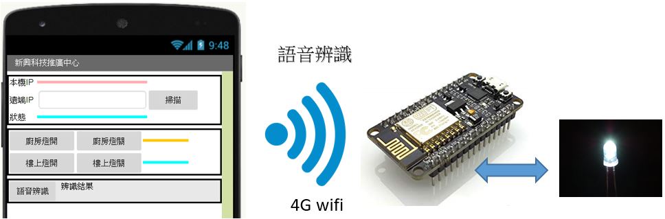

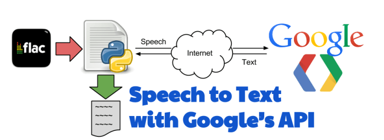
微軟(Microsoft face API)人臉辨識A應用網站
。 至於語音辨識的應用,我們是連結google 雲端的免費語音服務系統,結合App Invemtor的程式去開發自己的功能。